


Next: Baseline versus Antenna based
Up: Appendix: Calibration Principles
Previous: Appendix: Calibration Principles
Contents
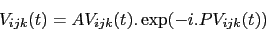
For any given complex number  , let us call
  its phase,
  its
amplitude, and
its
amplitude, and  its complex conjugate. The observed visibility
 is a complex number representing the amplitude and phase of
the signal detected on baseline
is a complex number representing the amplitude and phase of
the signal detected on baseline  , from spectral channel
  , at time
 ,
,
 |
(1) |
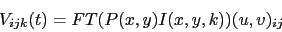
This visibility is the Fourier transform of the product of the primary beam
patterns of the antennas and the brightness distribution of the observed
source, sampled at the point
 corresponding to baseline
at time ,
corresponding to baseline
at time ,
 |
(2) |
where
 is the Fourier Transform operation,
  are integration
parameters,
are integration
parameters,
 is the brightness distribution of the source at frequency
,
is the brightness distribution of the source at frequency
,
-
 is the voltage pattern of antenna
  pointed in
direction
pointed in
direction  ,
,
 is the pointing direction of the antennas,
 is the pointing error of antenna , and
 are the projected coordinates of baseline , in
wavelength units.
are the projected coordinates of baseline , in
wavelength units.
If we further assume that all antennas are equal, their pointing errors are
negligible, their beam shape does not depend on the pointing direction, and
the fractional bandwidth is small (
 ), this equation
reduces to
), this equation
reduces to
 |
(3) |
where  is the power beam pattern of the antennas.
The antennas, receivers, cables, and correlators all introduce additional
modifications to this visibility. These perturbations can be formally
decomposed into
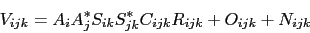 |
(4) |
where
 is the complex gain of antenna (amplitude and phase),
 is the complex gain of channel for antenna ,
 is the complex gain of channel for correlator entry
,
is the complex gain of channel for correlator entry
,
 is the theoretical visibility of the source,
 is a non random error on channel for correlator entry
. These errors have various origins, such as finite bandpass,
bandpass mismatch between antennas and
is a non random error on channel for correlator entry
. These errors have various origins, such as finite bandpass,
bandpass mismatch between antennas and  , etc...), and
 is a random error due to detection noise.
Provided the design of the interferometer system is adequate, the terms
appearing in this decomposition have the following properties:
 is normally distributed with known variance.
- is negligible with respect to . We will assume
 in the following discussion.
 is only weakly time dependent. This factor is introduced
essentially by analog filters in the correlator and residual (constant)
delay offsets between subbands; it may depend strongly on .
is only weakly time dependent. This factor is introduced
essentially by analog filters in the correlator and residual (constant)
delay offsets between subbands; it may depend strongly on .
 is only weakly time dependent. This factor is introduced
by receivers and IF cables. The frequency () dependence is weak.
is only weakly time dependent. This factor is introduced
by receivers and IF cables. The frequency () dependence is weak.
 depends on antenna pointing (amplitude only), focus
(amplitude and phase), and on atmosphere (amplitude and phase).
depends on antenna pointing (amplitude only), focus
(amplitude and phase), and on atmosphere (amplitude and phase).
Let
 to first order. Here,
  is a
random phase and
is a
random phase and  has known variance, <
 >. Then
 |
(5) |
 |
(6) |
where
 is the instrumental phase on antenna
 is the relative phase of channel for antenna
 is the relative phase of channel for correlator entry
, independent of the
is the relative phase of channel for correlator entry
, independent of the
 is the source phase on baseline for channel .
 only depends on through the coordinates of antennas
and , via
.
only depends on through the coordinates of antennas
and , via
.
 is a phase noise introduced by measurement noise
Then, to first order,
- can be measured independently, and is only weakly time
dependent,
- is constant, providing the receiver is not retuned,
- is time variable, on many different timescales, and
- has known variance, depending on
 /< >.
/< >.
Similar relations can be expressed for the intensities:
 |
(7) |
and
 |
(8) |
where
 is the gain of antenna (including effects due to
atmospheric absorption, focus, receiver gain, pointing, etc...),
is the gain of antenna (including effects due to
atmospheric absorption, focus, receiver gain, pointing, etc...),
 is the relative gain of channel for antenna ,
 is the relative gain of channel for correlator entry
 , measured independently from ,
 is the Source intensity on baseline .
  depends on only through antenna coordinates.
 has known variance <>.
The purpose of calibration is to determine as best as possible these
various functions, taking advantage of the time independence of some
parameters, and of the weak chromaticity of the atmosphere.
Next: Baseline versus Antenna based
Up: Appendix: Calibration Principles
Previous: Appendix: Calibration Principles
Contents
Gildas manager
2014-07-01