|


|
|


|
In most projects we observe, alternatively to the source(s), one or
two phase calibrators, for which `ideal' phases (without instrumental
contribution) are known to be zero for all the baselines. The track of
these phases allows us to measure and remove possible instrumental
contributions. The phase fittings for the calibrators observed
cyclically with the source (set by Select, Sect. ![[*]](crossref.png) )
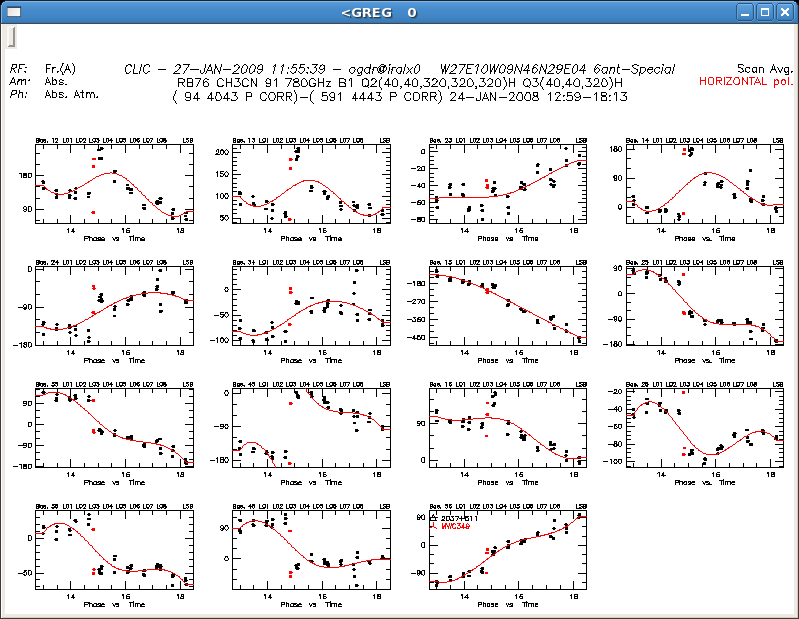
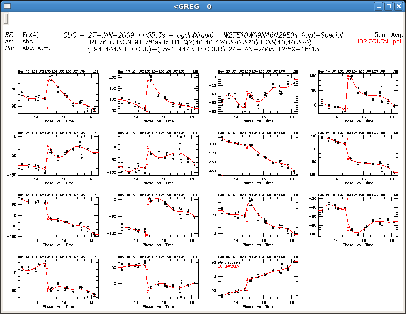
are obtained with the command ``solve phase /plot''. Breaks and jumps
can be introduced in the fit with the option ``solve phase /break `break_degree' `break_time' ''. Break_degree is the
order of the polynomial derivative that is discontinuous at the break
point, the sharpest one being 0. Break_time is the UT time
(h) at which the break should happen. (See two examples of phase
calibration in Figure
)
are obtained with the command ``solve phase /plot''. Breaks and jumps
can be introduced in the fit with the option ``solve phase /break `break_degree' `break_time' ''. Break_degree is the
order of the polynomial derivative that is discontinuous at the break
point, the sharpest one being 0. Break_time is the UT time
(h) at which the break should happen. (See two examples of phase
calibration in Figure ![[*]](crossref.png) .) The option ``/weight'' can be
used to take into account the weight (
.) The option ``/weight'' can be
used to take into account the weight (![]() SNR) of the different
calibrators, and ``/polynomial'' to impose polynomials of a given
degree (the last option is incompatible with the use of breaks). More
information can be found in the CLIC manual, or by typing ``help
solve phase'' in CLIC. The procedure pauses after proposing a fit. A
previous solution can be removed from the plot with ``clear seg'' to
try a new one. A solution is accepted by entering ``c'' in the line of
commands. The phases are calibrated independently for each
polarization, and stored in the hpb file at the end of the
procedure.
SNR) of the different
calibrators, and ``/polynomial'' to impose polynomials of a given
degree (the last option is incompatible with the use of breaks). More
information can be found in the CLIC manual, or by typing ``help
solve phase'' in CLIC. The procedure pauses after proposing a fit. A
previous solution can be removed from the plot with ``clear seg'' to
try a new one. A solution is accepted by entering ``c'' in the line of
commands. The phases are calibrated independently for each
polarization, and stored in the hpb file at the end of the
procedure.
The choice of phase calibrators used to calibrate the source phases
and amplitudes is performed by Select (see
Sect. ![[*]](crossref.png) ). If you disagree with the choice, it can be
modified with ``let phcal `list_of_calibrators' ''. The
phases and amplitudes of the calibrators not included in this ` list_of_calibrators' are self-calibrated. Note that if the
frequency-averaged phases from H and V polarization receivers are not
equal (which for instance can be seen in the RF phases plot, see
Sect.
). If you disagree with the choice, it can be
modified with ``let phcal `list_of_calibrators' ''. The
phases and amplitudes of the calibrators not included in this ` list_of_calibrators' are self-calibrated. Note that if the
frequency-averaged phases from H and V polarization receivers are not
equal (which for instance can be seen in the RF phases plot, see
Sect. ![[*]](crossref.png) ) self-calibration should be avoided, and
hence ``let phcal `*' '' should be entered after Select
(Sect.
) self-calibration should be avoided, and
hence ``let phcal `*' '' should be entered after Select
(Sect. ![[*]](crossref.png) ).
).
If due to some poor data obtained in a limited time interval, the fit fails in other interval in which the phases seem well constrained, we can divide the phase calibration in two parts, by specifying the scan intervals in the main calibration widget. We should just pay attention that no source data remains uncalibrated between the two selected intervals.
From time to time the procedure crashes because too many calibrator
data are flagged for an antenna or baseline. To find a proper solution
for the other baselines we can just mask (see point 2 in
Sect. ![[*]](crossref.png) ) whichever the flags, solve the phases for all
baselines, and reset at the end these masks. Verify at the end that
the source data that were calibrated with flagged calibrator data are
not used.
) whichever the flags, solve the phases for all
baselines, and reset at the end these masks. Verify at the end that
the source data that were calibrated with flagged calibrator data are
not used.
If the data obtained for a calibrator are too bad, and are not needed
in the calibration, we can flag them as indicated in Sect. ![[*]](crossref.png) .
.